Writing a Linux DRM Panel Driver for an ILI9488 MIPI DSI Display
June 13, 2026
Intro
I needed a display for a project where the number of wires in the display harness mattered and the display still had to update at a 60Hz frame rate. That's where MIPI DSI is a good fit. If you want high FPS you can use a parallel RGB interface, but you pay for it with dragging a bunch of wires. If you use a byte-addressable SPI display, the wiring is simple, but the frame rate usually less than ideal. DSI provides a ton of bandwith over few differential lines and has good support in many embedded Linux SoCs.
A DSI panel has to fit into the Linux DRM/KMS pipeline, attach to a DSI host, expose a valid display mode, and receive the right command sequence before anything appears on the glass. That's what this article is about.
The panel in question is Focus LCDs E35GH-I-MW800-CB, a 3.5 inch 320x480 IPS display built around the Ilitek ILI9488 controller. It uses a single-lane MIPI DSI interface for the display and a GT911 controller over I2C for touch. Target SoC was STM32MP157 - a proven workhorse for embedded Linux applications, so I used STM32MP157-DK1 board for bringup.
Since writing the first version of this driver I did upstream it. It has started its way into mainline through the DRM miscellaneous tree as drm/panel: Add Ilitek ILI9488 controller driver.
Still, the interesting part of this article is the bring-up itself: understanding how the panel fits into Linux DRM, getting the DSI host to attach, translating datasheet values into a struct drm_display_mode, and proving that the hardware path works.
Source code for this experiment also lives on my Github.
Hardware Overview
The display module is a fairly typical small embedded LCD:
320x480 pixels
3.5 inch IPS panel
ILI9488 TFT controller
1-lane MIPI DSI interface
GT911 capacitive touch controller over I2C
3.3V panel supply
Separate LED backlight supply
The important detail is that this is not a parallel RGB panel and not an SPI panel. The pixel data arrives over MIPI DSI, which means the Linux display pipeline needs a DSI host controller and a D-PHY, not just a GPIO bit-banged bus or a memory-mapped framebuffer.
The module connector also exposes only one data lane plus the clock lane. That may sound limiting, but for 320x480 it is more than enough. Let's do some "quick maths" ©...
The panel is configured for packed RGB666, so every pixel needs 18 bits. If we only count visible pixels at 60 Hz, the required payload bandwidth is:
320 * 480 * 60 * 18 = 165,888,000 bit/s
So the visible image data needs about 166 Mbit/s. The DRM mode used by the driver has a 14.4 MHz pixel clock, which includes blanking:
htotal = 320 + 60 + 20 + 42 = 442
vtotal = 480 + 20 + 10 + 33 = 543

14,400,000 / (442 * 543) = 59.9985 Hz
For a conservative DSI link estimate, multiply the full pixel clock by 18 bits per pixel:
14,400,000 * 18 = 259,200,000 bit/s
That puts the one-lane data rate at about 259 Mbit/s.
The generic MIPI D-PHY limit is much higher than this. The current MIPI D-PHY spec reaches 9 Gbit/s on a standard channel, and 11 Gbit/s on a short channel. That is not what constrains this board, though. The STM32MP157 side is the tighter and more relevant limit here. In Linux, the STM DSI driver starts with a per-lane ceiling of 500 Mbit/s and doubles it to 1 Gbit/s depending on the DSI hardware. Against the conservative 500 Mbit/s limit:
259.2 / 500 = 0.5184
So this mode uses about half of one lane even in the conservative case.
For the bench setup I used the display connector on STM32MP157 DK1. The DK1 DSI output is exposed through a 20-pin 1.0 mm pitch FFC connector, while the display module uses a 20-pin 0.5 mm pitch connector. That means the adapter needs to solve both pin mapping and pitch conversion. I used Uxcell 20 Pin 0.5mm 1mm Pitch to DIP converter board I got from Amazon, cut traces on one side and thrown some wires on top (see below).
Here's how the adapter schematic looks:

 Figure 1. Schematic mapping the DSI devkit connector to the panel connector
J3 is the backlight connector. Ideally this goes to a proper LED driver. If the display is just being brought up on the bench, it can also be driven from an external current source. The truth is that current sources are not always sitting around on every bench, so I used a DC bench supply with a small series resistor instead. The resistor matters because the LED strip has low dynamic impedance, and the maximum backlight current is only 60 mA. Connecting straight to the power supply is a good way to burn the LEDs.
For this panel, the minimum set of signals is:
MIPI clock lane: CLP / CLN
MIPI data lane 0: D0P / D0N
RESET
VCI / IOVCC
GND
LEDA / LEDK for backlight
The touch controller is a separate topic. Since GT911 already has mainline kernel support, the display panel driver does not need to know about the touch controller. Going forward I'm going to skip touch and focus on panel bringup. Enabling touch will be as easy as adding an I2C device node in Device Tree.
With the schematic done, the adapter itself is exactly as glamorous as expected for early display bring-up. Figure 2 shows the 0.5 mm display side, and Figure 3 shows the 1.0 mm DK1 side.
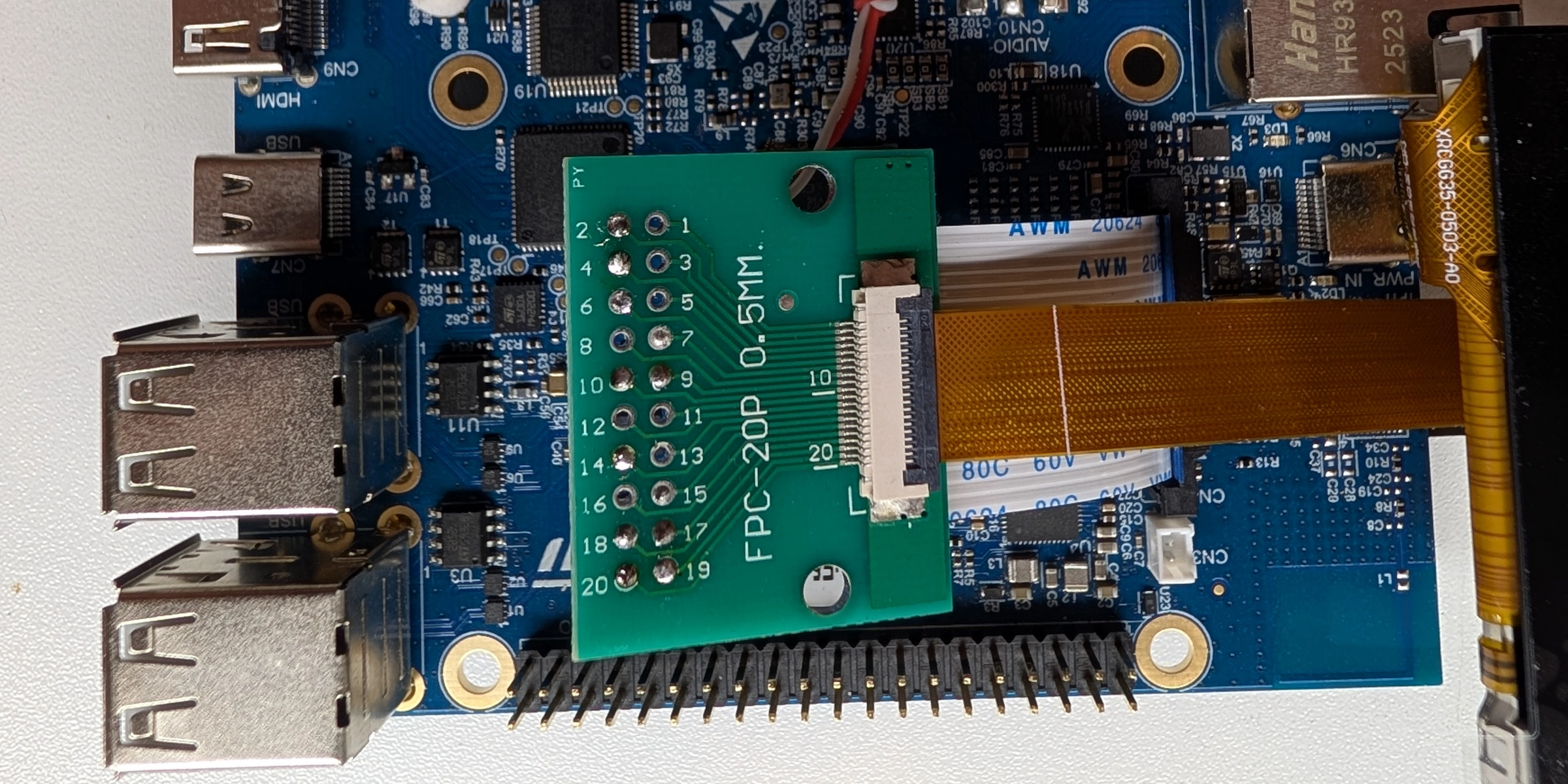
Figure 2. Business in the front - 0.5mm display connector
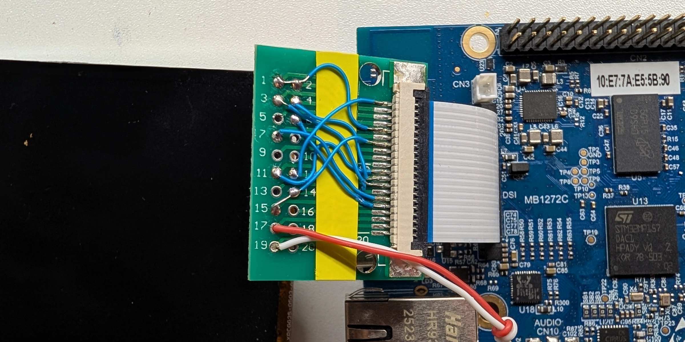
Figure 3. Party in the back - 1.0mm pitch coming from STM32MP157-DK1 with wiring according to Fig.1
For a large DSI panel this kind of wiring probably wouldn't fly due to signal integrity issues. But as you remember the data rate we're dealing with is about 259 Mbit/s. In DSI terms this translates to a D-PHY DDR clock about 129 MHz. So the bit period is about 3.9 ns. When it comes to wiring, a few millimeters of mismatch are in the tens of picoseconds range, not anywhere near a full bit time. So that kind of thing works without problem, it's not a multi-gigabit link anyways.
Where the Driver Fits
The Linux display stack is split into several pieces. Userspace gives DRM that framebuffer and asks for a modeset. DRM then routes it through objects that model the display pipeline:
framebuffer → plane → CRTC → encoder/bridge → DSI host → D-PHY → panel
In DRM/KMS terms, a framebuffer is not /dev/fb0 style fbdev. It is a piece of memory containing pixels, plus metadata such as size, stride and pixel format.
A plane is an image source: framebuffer, format, position and maybe scaling or blending.
A CRTC is the scanout engine. It owns the display timing and turns memory into a timed pixel stream: active pixels, blanking, sync pulses and frame boundaries.
On STM32MP157, LTDC is the CRTC-side block.
After the CRTC, the stream has to leave the SoC in some physical format. Encoders and bridges represent that output side: the part that adapts the CRTC's pixel stream to HDMI, LVDS, DSI, DPI, or whatever the board wires out. For this board the relevant output path is:
LTDC → DSI host → D-PHY → panel
The DSI host packetizes the LTDC pixel stream as MIPI DSI video packets. It also provides the command path for DCS initialization commands. The D-PHY is the electrical layer, and the panel is the sink that receives both commands and video data.
The panel driver is only responsible for the last part of this chain. It does not allocate framebuffers, implement modesetting, or know how the SoC display controller works. Instead, it tells DRM a few very specific things:
- What display mode the panel supports
- How many DSI lanes it uses
- What DSI pixel format it expects
- What DSI mode flags are required
- How to power the panel on and off
- How to reset the panel
- Which DCS commands initialize the controller
This is a nice division of labor. The panel driver describes the glass and controller behavior. The SoC-specific DRM driver handles the display engine and DSI host.
In Linux this kind of driver is usually implemented with struct drm_panel and registered as a mipi_dsi_driver.
That gives us the skeleton:
static struct mipi_dsi_driver ili9488_dsi_driver = {
        .probe  = ili9488_dsi_probe,
        .driver = {
                .name           = "ili9488-dsi",
                .of_match_table = ili9488_of_match,
        },
};
module_mipi_dsi_driver(ili9488_dsi_driver);
Once the DSI device appears from Device Tree, the MIPI DSI core calls probe() and the panel driver gets a chance to configure and attach itself.
Describing the Panel
I started with a small descriptor structure. This is a common pattern in DRM panel drivers because many display controllers are used across several slightly different modules. The controller may be the same, but the init sequence, timing, orientation or lane count can differ per actual panel.
struct ili9488_desc {
        const struct drm_display_mode *display_mode;
        unsigned long mode_flags;
        enum mipi_dsi_pixel_format format;
        unsigned int lanes;
        unsigned int bpc;
        void (*init_sequence)(struct mipi_dsi_multi_context *ctx);
};

struct ili9488 {
        struct drm_panel panel;
        struct mipi_dsi_device *dsi;
        struct gpio_desc *reset;
        struct regulator_bulk_data supplies[2];
        const struct ili9488_desc *desc;
        enum drm_panel_orientation orientation;
};

static const char * const regulator_names[] = {
        "vci",
        "iovcc",
};
The ili9488_desc is the mostly-static information about a particular panel module.
The ili9488 structure is the runtime driver state: the DRM panel object, the DSI device, reset GPIO, power supplies, and orientation.
For this specific display the descriptor is:
static const struct ili9488_desc e35gh_i_mw800cb_desc = {
        .init_sequence = e35gh_i_mw800cb_init,
        .display_mode = &e35gh_i_mw800cb_display_mode,
        .mode_flags = MIPI_DSI_MODE_VIDEO | MIPI_DSI_MODE_VIDEO_SYNC_PULSE |
                      MIPI_DSI_MODE_LPM | MIPI_DSI_CLOCK_NON_CONTINUOUS,
        .format = MIPI_DSI_FMT_RGB666_PACKED,
        .lanes = 1,
        .bpc = 6,
};
There are couple of important choices here.
The panel uses one DSI lane, matching the datasheet and the connector pinout. The pixel format is packed RGB666, because the init sequence programs the ILI9488 for 18-bit pixels.
According to the datasheet, ILI9488 supports MIPI_DSI_FMT_RGB666 format which is 6-bit per chanel loosely packed into 24-bit stream. I never managed to get it to work though.
That also means the panel reports 6-bits per color channel through bpc.
The mode flags were the tricky part. Different DSI hosts support modes differently, and this panel was picky about details such as continuous vs non-continuous clock.
One wrong flag can be the difference between a working panel and a black screen.
The driver also uses DSI video mode. In video mode the host continuously streams pixel data according to the selected display timing, which is how most LCD panels are driven in Linux DRM.
DCS Commands and the Init Sequence
MIPI DSI is not just a pixel pipe. It can also carry commands. For display panels those commands commonly follow MIPI DCS, the Display Command Set. DCS commands are used for things like sleep mode, display on/off, pixel format and address mode. Panel vendors also tend to require controller-specific commands for gamma curves, power settings and VCOM configuration.
The correct init sequence is not something you can reliably derive from the controller datasheet alone. Only the panel manufacturer really knows it, because the sequence depends not just on the controller, but also on the glass, electrical configuration and manufacturing process. If you are lucky, the manufacturer publishes the sequence somewhere on their website. For this module FocusLCDs provides an E35GH-I-MW800-CB init file, which is exactly the kind of starting point you want for bring-up.
For this panel the init sequence starts like this:
static void e35gh_i_mw800cb_init(struct mipi_dsi_multi_context *ctx)
{
        /* Gamma control 1,2 */
        mipi_dsi_dcs_write_seq_multi(ctx, 0xE0, 0x00, 0x10, 0x14, 0x01,
                                     0x0E, 0x04, 0x33, 0x56, 0x48, 0x03,
                                     0x0C, 0x0B, 0x2B, 0x34, 0x0F);
        mipi_dsi_dcs_write_seq_multi(ctx, 0xE1, 0x00, 0x12, 0x18, 0x05,
                                     0x12, 0x06, 0x40, 0x34, 0x57, 0x06,
                                     0x10, 0x0C, 0x3B, 0x3F, 0x0F);

        /* Power control 1,2 */
        mipi_dsi_dcs_write_seq_multi(ctx, 0xC0, 0x0F, 0x0C);
        mipi_dsi_dcs_write_seq_multi(ctx, 0xC1, 0x41);

        /* VCOM Control */
        mipi_dsi_dcs_write_seq_multi(ctx, 0xC5, 0x00, 0x25, 0x80);
        mipi_dsi_dcs_write_seq_multi(ctx, 0x36, 0x48);

        /* Interface pixel format 18bpp */
        mipi_dsi_dcs_write_seq_multi(ctx, 0x3A, 0x66);
        mipi_dsi_dcs_write_seq_multi(ctx, 0xB0, 0x00);
        mipi_dsi_dcs_write_seq_multi(ctx, 0xB1, 0xA0);
        mipi_dsi_dcs_write_seq_multi(ctx, 0xB4, 0x02);
        mipi_dsi_dcs_write_seq_multi(ctx, 0xB6, 0x02, 0x02, 0x3B);
        mipi_dsi_dcs_write_seq_multi(ctx, 0xE9, 0x00);
        mipi_dsi_dcs_write_seq_multi(ctx, 0xF7, 0xA9, 0x51, 0x2C, 0x82);
        mipi_dsi_dcs_write_seq_multi(ctx, 0x21);
}
One nice modern helper here is mipi_dsi_multi_context.
Instead of checking the return value after every single DCS write, the calls accumulate errors in ctx.accum_err.
That makes long panel initialization sequences much easier to read.
After the panel-specific commands are sent, activation finishes with standard DCS commands:
static int ili9488_activate(struct ili9488 *ili)
{
        struct mipi_dsi_multi_context ctx = { .dsi = ili->dsi };

        if (ili->desc->init_sequence)
                ili->desc->init_sequence(&ctx);

        mipi_dsi_dcs_exit_sleep_mode_multi(&ctx);
        mipi_dsi_msleep(&ctx, 120);
        mipi_dsi_dcs_set_display_on_multi(&ctx);

        return ctx.accum_err;
}
The 120 ms delay after sleep-out is very typical for display controllers. That is one of those places where it is tempting to "optimize" the wait time during bring-up. This temptation should be resisted until everything works. Displays have enough ways to fail already.
Power and Reset
Display panels are usually sensitive to power sequencing.
For this panel the driver uses two named supplies, vci and iovcc, plus a reset GPIO:
static int ili9488_power_on(struct ili9488 *ili)
{
        struct mipi_dsi_device *dsi = ili->dsi;
        int ret;

        ret = regulator_bulk_enable(ARRAY_SIZE(ili->supplies), ili->supplies);
        if (ret < 0) {
                dev_err(&dsi->dev, "regulator bulk enable failed: %d\n", ret);
                return ret;
        }

        gpiod_set_value_cansleep(ili->reset, 0);
        usleep_range(1000, 5000);
        gpiod_set_value_cansleep(ili->reset, 1);
        usleep_range(1000, 5000);
        gpiod_set_value_cansleep(ili->reset, 0);
        usleep_range(5000, 10000);

        return 0;
}

static int ili9488_power_off(struct ili9488 *ili)
{
        struct mipi_dsi_device *dsi = ili->dsi;
        int ret;

        gpiod_set_value_cansleep(ili->reset, 1);

        ret = regulator_bulk_disable(ARRAY_SIZE(ili->supplies), ili->supplies);
        if (ret)
                dev_err(&dsi->dev, "regulator bulk disable failed: %d\n", ret);

        return ret;
}
The reset GPIO is described with GPIO polarity in Device Tree. That means the driver can use logical reset values and let the GPIO descriptor handle whether the physical line is active low or active high. This is one of those small kernel APIs that quietly saves you from hardcoding board-level electrical details into the driver.
The panel's prepare() callback powers on the panel and sends the init sequence:
static int ili9488_prepare(struct drm_panel *panel)
{
        struct ili9488 *ili = panel_to_ili9488(panel);
        int ret;

        ret = ili9488_power_on(ili);
        if (ret)
                return ret;

        ret = ili9488_activate(ili);
        if (ret) {
                ili9488_power_off(ili);
                return ret;
        }

        return 0;
}
The opposite path sends display-off and sleep-in commands before disabling power:
static int ili9488_deactivate(struct ili9488 *ili)
{
        struct mipi_dsi_multi_context ctx = { .dsi = ili->dsi };

        mipi_dsi_dcs_set_display_off_multi(&ctx);
        mipi_dsi_dcs_enter_sleep_mode_multi(&ctx);
        mipi_dsi_msleep(&ctx, 120);

        return ctx.accum_err;
}
DRM calls these panel hooks as part of the larger modeset sequence. The panel driver gets a local and understandable lifecycle, while the rest of the display pipeline remains SoC-specific.
Display Mode
The panel also needs a fixed display mode. This is where datasheet values turn into DRM timing fields:
static const struct drm_display_mode e35gh_i_mw800cb_display_mode = {
        .clock = 14400,

        .hdisplay = 320,
        .hsync_start = 320 + 60,
        .hsync_end = 320 + 60 + 20,
        .htotal = 320 + 60 + 20 + 42,

        .vdisplay = 480,
        .vsync_start = 480 + 20,
        .vsync_end = 480 + 20 + 10,
        .vtotal = 480 + 20 + 10 + 33,

        .width_mm = 48,
        .height_mm = 73,

        .flags = DRM_MODE_FLAG_NHSYNC | DRM_MODE_FLAG_NVSYNC,
        .type = DRM_MODE_TYPE_DRIVER | DRM_MODE_TYPE_PREFERRED,
};
The hdisplay and vdisplay fields are the visible resolution.
The sync start, sync end and total values include the porches and sync pulse widths.
I set pretty conservative porches here which I believe more than the panel itself actually requires.
But with shorter porches I had problems with one of the SoC I tested the driver on - TI AM62P. The display
controller was not happy with that for some reason.
With htotal = 442, vtotal = 543, and a 14.4 MHz pixel clock, the refresh rate is essentially 60 Hz:
14,400,000 / (442 * 543) = 59.9985 Hz
That is why the DRM mode clock is 14400, expressed in kHz. The slightly rounder clock also proved easier to synthesize on the STM32MP157 DSI/LTDC side.
The mode is exposed with:
static int ili9488_get_modes(struct drm_panel *panel,
                             struct drm_connector *connector)
{
        struct ili9488 *ili = panel_to_ili9488(panel);
        const struct drm_display_mode *mode = ili->desc->display_mode;

        connector->display_info.bpc = ili->desc->bpc;

        return drm_connector_helper_get_modes_fixed(connector, mode);
}
For a simple embedded panel this is all we need. It supports exactly one known display mode wired into the board.
Probe Function
Now let's look at how everything is tied together during probe:
static int ili9488_dsi_probe(struct mipi_dsi_device *dsi)
{
        struct device *dev = &dsi->dev;
        struct ili9488 *ili;
        int i, ret;

        ili = devm_drm_panel_alloc(dev, struct ili9488, panel,
                                   &ili9488_funcs,
                                   DRM_MODE_CONNECTOR_DSI);
        if (IS_ERR(ili))
                return PTR_ERR(ili);

        ili->desc = device_get_match_data(dev);
        ili->dsi = dsi;

        dsi->mode_flags = ili->desc->mode_flags;
        dsi->format = ili->desc->format;
        dsi->lanes = ili->desc->lanes;
        ...
}
The DSI parameters are written directly into the mipi_dsi_device.
That is how the panel tells the DSI host what kind of link it needs.
Then the driver acquires resources described in Device Tree:
ili->reset = devm_gpiod_get(dev, "reset", GPIOD_OUT_LOW);
if (IS_ERR(ili->reset))
        return dev_err_probe(dev, PTR_ERR(ili->reset),
                             "failed to get reset-gpios\n");

for (i = 0; i < ARRAY_SIZE(ili->supplies); i++)
        ili->supplies[i].supply = regulator_names[i];

ret = devm_regulator_bulk_get(dev, ARRAY_SIZE(ili->supplies),
                              ili->supplies);
if (ret < 0)
        return dev_err_probe(dev, ret, "failed to get regulators\n");

ret = of_drm_get_panel_orientation(dev->of_node, &ili->orientation);
if (ret)
        return dev_err_probe(dev, ret, "failed to get orientation\n");

ret = drm_panel_of_backlight(&ili->panel);
if (ret)
        return dev_err_probe(dev, ret, "failed to get backlight\n");
The backlight is worth calling out. The LCD controller and the LED backlight are separate pieces of hardware. This panel's backlight wants a higher LED voltage than the 3.3V logic supply, so it belongs in the board design and Device Tree as a separate backlight device. The panel driver merely asks DRM to connect it.
Finally the panel is registered and attached to the DSI host:
ili->panel.prepare_prev_first = true;

ret = devm_drm_panel_add(dev, &ili->panel);
if (ret)
        return ret;

ret = devm_mipi_dsi_attach(dev, dsi);
if (ret < 0)
        return dev_err_probe(dev, ret, "failed to attach to DSI host\n");
If this attach step fails, the problem may not be in the panel driver at all. It can mean the DSI host did not probe, the Device Tree graph is wrong, clocks are missing, the PHY is disabled, or the driver simply cannot support the requested link configuration.
Device Tree
The driver is only half of the story. The other half is describing how the panel is connected to the SoC display pipeline. For the STM32MP157 DK1, the important path is:
LTDC → DSI → panel
The SCMI board variant I used needs the DSI supply and clocks described explicitly:
&dsi {
phy-dsi-supply = <®18>;
clocks = <&rcc DSI>, <&scmi_clk CK_SCMI_HSE>, <&rcc DSI_PX>;
};
For quick bring-up I also described the backlight as a GPIO-controlled backlight. On a real board this would normally sit behind the LED driver that actually supplies the backlight current:
/ {
        panel_backlight: panel-backlight {
                compatible = "gpio-backlight";
                gpios = <&gpioa 15 GPIO_ACTIVE_HIGH>;
                default-on;
        };
};
Then the DSI host gets the panel as a child device:
&dsi {
        #address-cells = <1>;
        #size-cells = <0>;
        status = "okay";

        panel@0 {
                compatible = "focuslcds,e35gh-i-mw800cb", "ilitek,ili9488";
                reg = <0>;
                vci-supply = <&v3v3>;
                iovcc-supply = <&v3v3>;
                reset-gpios = <&gpioe 4 GPIO_ACTIVE_LOW>;
                backlight = <&panel_backlight>;

                port {
                        panel_in: endpoint {
                                remote-endpoint = <&dsi_out>;
                        };
                };
        };
};
Finally the graph connects LTDC to DSI, and DSI to the panel:
&dsi_in {
remote-endpoint = <<dc_ep1_out>;
};
&dsi_out {
remote-endpoint = <&panel_in>;
};
<dc {
status = "okay";
port {
#address-cells = <1>;
#size-cells = <0>;
ltdc_ep1_out: endpoint@1 {
reg = <1>;
remote-endpoint = <&dsi_in>;
};
};
};
This graph syntax can look a little ceremonial at first, but it captures an important fact: display pipelines are made of connected components. The panel is not just "under" the DSI host. It is connected to the DSI output endpoint, the DSI input endpoint is connected to LTDC, and LTDC is the block actually scanning pixels out from memory.
For a proper board description the panel node also needs to describe power and backlight resources. The binding for this driver requires:
required:
  - compatible
  - reg
  - vci-supply
  - iovcc-supply
  - reset-gpios
  - backlight
  - port
During quick bring-up it is easy to cheat with always-on rails or manually controlled backlight power. That is fine for the bench, but not a good hardware description. Device Tree should describe the board as it actually is, not as we temporarily wish it was.
Binding
The Device Tree binding is small:
title: Ilitek ILI9488 based MIPI-DSI panels

properties:
  compatible:
    items:
      - enum:
          - focuslcds,e35gh-i-mw800cb
      - const: ilitek,ili9488

  reg:
    maxItems: 1

  vci-supply: true
  iovcc-supply: true

required:
  - compatible
  - reg
  - vci-supply
  - iovcc-supply
  - reset-gpios
  - backlight
  - port

unevaluatedProperties: false
The compatible string is intentionally specific. Even though the controller is ILI9488, the panel module matters. Different modules using the same controller can have different reset timing, power rails, physical dimensions, orientation, gamma settings, lane counts and backlight wiring.
Building Out of Tree
For early bring-up I built the driver as an external module against a checked-out kernel tree:
KERNEL_DIR ?= /home/irz/kernel/linux

PWD := $(shell pwd)

obj-m := panel-ilitek-ili9488.o

ARCH ?= arm
CROSS_COMPILE ?= arm-linux-gnueabihf-

all:
        $(MAKE) -C $(KERNEL_DIR) M=$(PWD) ARCH=$(ARCH) CROSS_COMPILE=$(CROSS_COMPILE) modules

clean:
        $(MAKE) -C $(KERNEL_DIR) M=$(PWD) clean
This is not a replacement for integrating the driver into drivers/gpu/drm/panel, but it is a very convenient way to iterate during hardware bring-up.
To make the iteration loop less annoying, I also changed U-Boot to boot the kernel over TFTP and mount the root filesystem over NFS. That way the board always boots the kernel and rootfs from my development machine, and I do not need to copy images to an SD card or flash storage after every change.
The important detail is that the panel driver does not require a full kernel rebuild for every experiment.
I could change an init command, rebuild only the external .ko, drop the new module into the exported NFS rootfs, and try again on the target.
For early panel bring-up, that is much faster.
For upstreaming, this turned into the usual in-tree pieces:
MAINTAINERS
drivers/gpu/drm/panel/panel-ilitek-ili9488.c
drivers/gpu/drm/panel/Kconfig
drivers/gpu/drm/panel/Makefile
Documentation/devicetree/bindings/display/panel/ilitek,ili9488.yaml
But again, this article is not really about the mechanics of submission. If interested, I described my experiences with upstreaming process in hwmon driver article.
What Can Go Wrong
The annoying thing about display bring-up is that many failure modes look exactly the same - black screen.
Some examples:
| Failure | What to check |
|---|---|
| Backlight only | The panel may be working but the backlight is off. Or the backlight may be on while no pixels are being scanned out. Those are very different failures, but from a distance both look like "display does not work". |
| Wrong reset polarity | If reset polarity is wrong, the controller might never leave reset or might not receive the intended reset pulse. Using reset-gpios with proper polarity in Device Tree avoids hardcoding this in the driver. |
| DSI host did not attach | If devm_mipi_dsi_attach() fails, check the DSI host, clocks, PHY and graph endpoints before blaming the panel init sequence. |
| Wrong pixel format | The DCS pixel format command and dsi->format need to agree. For this driver the panel is programmed for 18bpp via (0x3A, 0x66), and the DSI device uses MIPI_DSI_FMT_RGB666_PACKED. |
| Wrong DSI mode flags | The mode flags describe how the host sends video and commands. If those do not match what the host and panel tolerate, the DSI host can attach and the init commands can still run, but the display may stay black. |
| Almost-correct timings | Wrong porch or sync values can produce shifted images, unstable refresh, or nothing at all. If you see the image, but somethig is wrong with it it's likely a timing issue. |
As always, oscilloscope helps greatly when in doubt that LPM mode init commands are coming through, if not sure that DSI host generates the video clock or reset is sequenced correctly. Just be careful with those differential signals. If you have such a luxury as active differential high-speed probe it's great. If not a regular probe can load them a lot, but at least you can see what's going on with the signal in general.
Conclusion
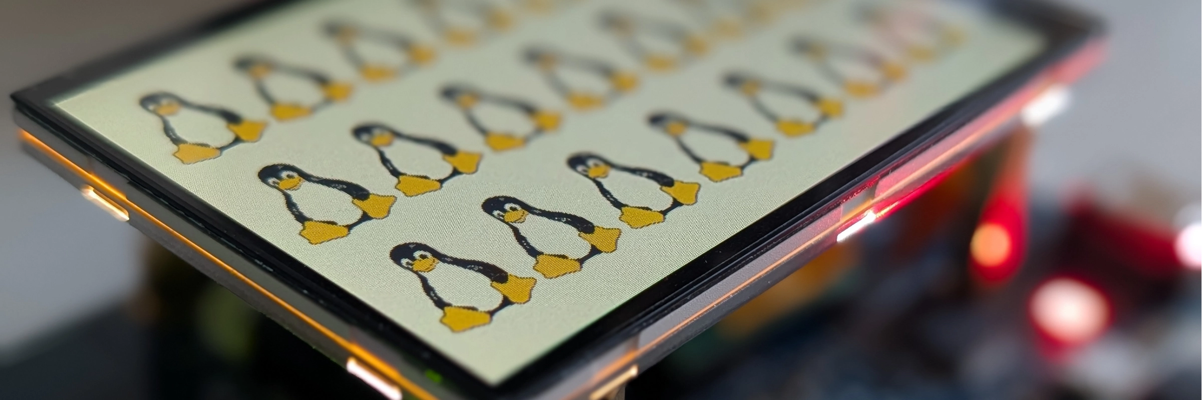
It's alive! 🐧
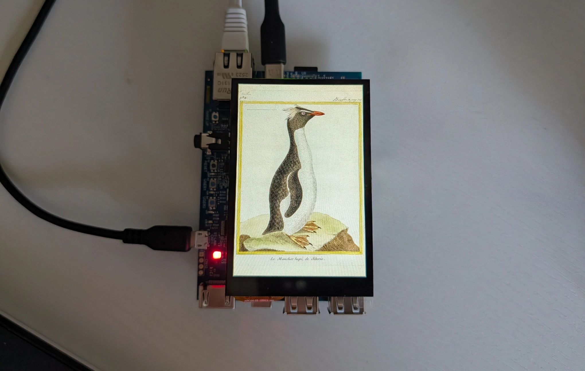
Figure 4. Plate 984, “Le Manchot hupé de Sibérie” from "Planches enluminées d’histoire naturelle" on the display
The translation of this 18th century hand-colored plate says "The crested penguin of Siberia". An interesting error, since I lived in Siberia most of my life and saw many penguins, but never one with a crest... The penguin species is without a doubt a member rockhopper penguins family.
Writing a simple DRM panel driver is mostly an exercise in describing hardware accurately.
The code itself is not very large: register a drm_panel, configure a mipi_dsi_device, provide a fixed display mode, handle power/reset, and send the panel initialization sequence.
The tricky part is that the driver sits at the end of a much longer chain. For the panel to light up, the Device Tree graph, DSI host, D-PHY, clocks, regulators, reset line, backlight and display mode all need to line up. When they do and the thing lights up - it still feels a little magical. The driver source for this post is available on Github.